
Putting electronic components into a cigar box guitar, and getting everything properly wired and connected, can be a daunting task for the first-timer – but it doesn’t have to be. In this article we will present several basic wiring diagrams created by Ted Crocker, and discuss each of them in some detail to help you understand what is going on.
Don’t forget that you can get most of the parts shown in this article, including piezos , jacks, volume potentiometers and potentiometer knobs , right in our C. B. Gitty Crafter Supply Web Store!
The basic concepts presented here can be built upon and experimented with in your own building adventures, with great results. It is important to remember that adding electronics to your CBG doesn’t have to be some kind of black magic. Granted, you can get extremely complicated with it, but the point is you don’t HAVE to. You can get good results and have a lot of fun with something as simple as a piezo, a length of wire and a jack.
We will present three different diagrams here: a simple piezo to jack setup; a piezo to jack with a volume pot added in; piezos wired in series and parallel to a jack; and a dual piezo setup that includes a 3-way switch for switching between the two piezos.
 One more thing before we can get started – it can make things a LOT easier if you use a jack with a nice long threaded shank that will reach through the side of a cigar box. The Neutrik-brand jacks we sell in our web store are selected specifically because they have a nice 9.5mm shaft length perfect for getting through a cigar box side with a minimum of gouging and thinning. This can save you a lot of time, and time is money, so check it out!
So enough talk, let’s get started!
Diagram #1: Wiring a Piezo to a Jack
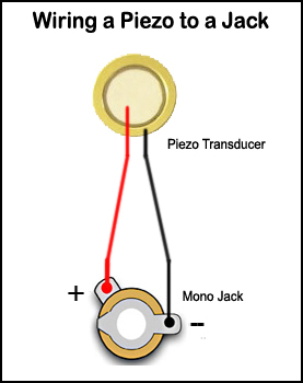 This diagram shows about the most basic wiring setup you can get: a single piezo transducer wired directly to a mono (two pole) jack. This is the setup that many first-time CBG builders use when looking to be able to plug their build into an amp. Many builders stick with this basic setup and never feel the need to get any fancier – and there is nothing wrong with that! This setup will give you a very straightforward sound, which is very dependent on where the piezo is placed and how it is mounted in the box – see our articles on piezo basics for more info on that.
One question that gets asked a lot is whether the polarity of what piezo wire you connect to which pole on the jack matters. Or in other words, does it matter which pole on the jack you wire the red or black wire to. The simple answer is that no, it doesn’t – you will get the same sound regardless of how you connect it. HOWEVER – it is a very good habit to always connect the ground (black wire) to the ground pole. With a straight piezo-to-jack it isn’t critical, but as wiring jobs get more complex it makes troubleshooting a LOT easier if you are consistent throughout!
The only other thing to note is that most piezos come with pretty short wire leads (in the range of 2 inches) that you will have to extend to reach your jack. Pretty much any kind of small-gauge copper wire will do – piezos do not require any special shielded wire or anything like that.
One more thing – DON’T WASTE YOUR MONEY AT RADIO SHACK. We sell a range of piezo sizes, both wired and unwired, in our C. B. Gitty Crafter Supply web store at great prices. Check it out!
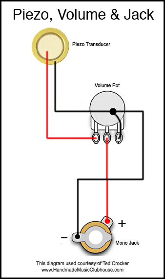 Diagram #2: Piezo, Volume Potentiometer and Jack
 This setup builds upon the concepts of the last diagram but adds one little twist – a volume potentiometer (pot) that allows you to control the output volume of the signal, in the same way that a volume knob on your stereo does. Really a pot is just a variable resistor that increases or decreases the total resistance as you turn it, which in turn allows more or less current through the circuit.
There are two main types of potentiometers available on the market, identified by the type of their “taper” – audio taper, and linear taper. We recommend always using audio taper pots for volume controls, as they will give you a smoother rate of increase and decrease. Also, for piezo volume control, a resistance rating of either 250KOms or 500KOhms is recommended, with 500KOhms being the one most builders go with.
As you can see from the diagram, one of the piezo leads (red) is wired to the first contact of the pot, and then continues off of the second contact and on to the jack. The other (black) is wired to the third contact of the pot and then on to the jack. As mentioned above, pretty much any smaller-gauge copper wire can be used for this purpose, and shielded wire is not required. Be careful when soldering to a pot though as it is possible to burn them out with too much heat. Tin your wires and don’t let the pot get too hot!
That is about it for this diagram. When wired up in this way and plugged into an amp, the total volume output by the piezo will be controlled by the potentiometer. Properly installed into a cigar box guitar, this will allow the player to make on-the-fly adjustments from the instrument, which definitely has its uses. Pots are pretty cheap and as we’ve seen they are not that hard to wire in, and can really be a nice extra touch for your CBG, especially from the point of view of a player.
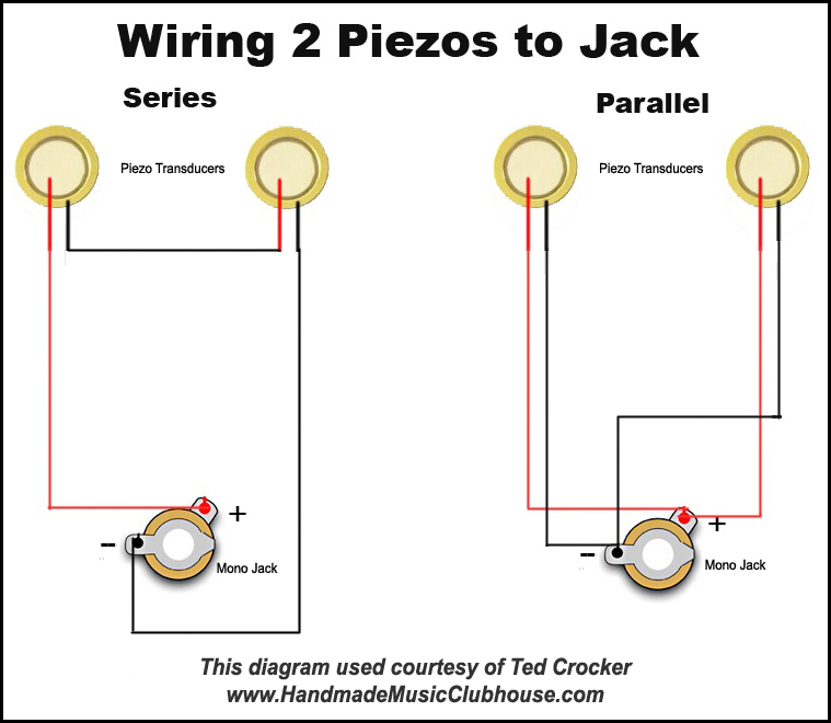
 This diagram shows two ways that multiple piezos can be wired to a single jack. It involves some basic electrical circuit theory – the concept of wiring in parallel and wiring in series.
Basically, wiring in series means attaching two or more components “end to end”, so that a single pair of wires ends up at the terminal, in this case the jack. The left portion of the diagram illustrates this – one lead from each piezo runs to the jack, and the other two leads are connected together. This in effect means that the electrical current that gets translated into sound always travels through both piezos, so that each affects the signal of the other. The effect of wiring in series is to increase the total impedence of the circuit, which can definitely have an effect on sound – a topic that is too advanced for this article.
Wiring in parallel differs in that each component has its own leads that run back to the terminal. As shown in the right side of the diagram, each piezo’s leads are directly connected to the jack. So instead of a single signal running through both piezos, each piezo sends its own distinct signal back to the jack, where they join and run to the amp.
There is some divided opinion amongst builders as to which is better, though in our opinion you will usually get better results with wiring in parallel as opposed to in series. In general, the higher the impedence of a circuit, the less current flows and that translates to less volume. But as with most things related to cigar box guitars, the best way to decide is to try both and see which sounds better to you. A good “controlled’ experiment would be to mount two piezos in a cigar box guitar build that has the inside accessible; then try them wired in parallel versus in series, and see which sounds better to you.
Diagram #4:
Multiple Piezos, 3-way Switch & Jack
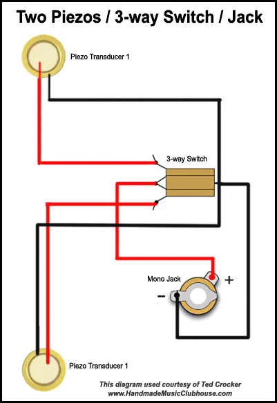 This diagram is the most advanced one yet, and the final one we will cover in this article. It involves the use of two piezos, a three-way switch and a jack. The purpose of the circuit is so that you can have two piezos in two different locations in your instrument, and switch between them while playing. In the far left (or right, depending on your wiring) switch position, you would have just the signal from piezo#1 getting to the amp. In the far right position, you would have just piezo #2. And in the center position, you would have both piezo one and two in parallel. This is similar to how electric guitars allow you to switch between different magnetic pickups, or blend them together, for different tonal qualities.
It should be noted that the black wires all are joined to the switch chassis on the right side of the switch in the diagram, while the red wires each are wired to a separate terminal, with the center terminal being the one that runs to the jack. The black wires are attached only as a “ground”, and they should not in any way make contact with the red “hot” wires. It is not always necessary to ground the black wires, but it is a good habit to get into.
To take this concept further, if you wanted to add a volume pot to this circuit, you could either add it between the switch and the jack, for a “master” volume control, or you could get even more adventurous and add two separate volume controls, one for each piezo. These would go between each piezo and the switch, and would allow a great deal of fine-tuning of the signal coming from each one. This diagram could also be expanded to support more piezos – either wired in series or in parallel. There are also switches available with more than three positions, which would allow even more flexibility (and wiring complexity) – but to be honest, we think there comes a point with a cigar box guitar where one has ventured into the realm of overkill. But the options are there!
Conclusion
Well, that completes our overview of basic piezo wiring diagrams for cigar box guitars. We hope that you have found it to be helpful, and that if you have been on the fence about wiring up your CBG you are now ready to dive in! There is of course a lot more that could said about this topic, and much more advanced diagrams that could be offered. We leave it up to you to experiment to your heart’s content, and see what kind of great (or not-so-great) sounds you can produce. As we often say with cigar box guitars (actually it’s more of a mantra): there are no rules. If you try something and don’t like it, rip it out and try something else! Of course when it comes to electronics, this is a lot easier if you don’t permanently seal your box. But if you did – well, it’s a great excuse to build another one!
Good luck with your electrified building!
I would appreciate your help with the cbg I want to build. I know that piezos are “hot” pickups. But, what I would like to do with this build is to install a piezo in both the neck and bridge positions, both pickups with a volume and tone pots, and a three-way switching option. Is this doable? Do you have any schematics available for this configuration? Thanks.
How can I wire up two piezo disks so that each one has it’s own volume and tone ?? I could do with a diagram and a description of the parts required
The white/quarts portion of the piezo is always positive. The brass portion will be ground.
Hi I’m new to the world of piezo. My first purchase came with red and black wires pretty straight forward. The next was for 35mm ones the only issue is both of the wires are the same color, and I’m not sure how to proceed. I’ve struck out on line hunting for a solution, so I thought give it a go and give you a hollar. This is my stress relief from winning the battle o0ver cancer twice. Any help in this would be so greatly appreic0ated. Have aaw2esome day and a even better one tomorrow Dave
i have a 3 string cigar box guitar with magnetic pickup,i would like more volume in acoustic form and am considering making two sound holes on the top of the box.would like your advice on the subject please,i am still learning and having fun with it,thanks yours j lynch
I’m afraid to say that’s a bit more complicated than we have gotten into, but I have some ideas.
If looking at the bottom of the pot and 1-3 is left to right, lug 3 (to the best of my knowledge) is used for grounding purposes. Lug 1 is your input and lug 2 is your output. I am not sure you will get the intended results by wiring it that way.
If you attach the disc piezo to a volume or tone pot and then connecting it along with your rod piezo to the pre-amp in parallel wiring, you may be able to use the pot to help balance some of the wilder frequencies from the disc piezo, and then use the pre-amp to blend the two before it is pushed to the amplifier.
Another option to try is to solder a .01 directly to the piezo (we have a how-to video on this process). This will help tame the disc piezo as well. If you then wire that with your rod-piezo to the pre-amp it may help blend it nicely.
All of this is in the realm of speculation. I haven’t actually attempted any of the above, so I cannot guarantee how well it will all work.
For the Pot value, 500kohm is a fairly standard rating for disc piezos, with 250kohm and a .01 or .022 capacitor for tone.
If you do decide to go ahead with it, I’d be interested to hear how it shakes out.
Hello there.
Great info. I have a small question
The setup I am thinking about is:
1 piezo undersaddle
1 piezo sensor (circle type) on body
1 preamp
A linear potentiometer on lug 1 piezo A on lug 3 piezo B mid lug connected to preamp.
My question:
Will such a setup work? The idea of the pot is to work like a balance between the two. I have no idea what type of pot to use. Any advice is welcome.
Thank you
Hey there Jim, Great question.
For the Volume pot, the numbers generally stand for the following:
1) This is your ground. Many bend it back and solder it directly to the back casing of the pot, or bridge with a piece of wire.
2) This is your output wire. This is where you will solder the wire going to the positive terminal on your jack or tone potentiometer.
3) This is your input. This is where the positive wire from the pickup is soldered.
If you are wiring up a tone pot, the layout is the same. The only difference is you will be soldering a capacitor from the first lug to the back of the pot as part of the ground.
Hope that helps!
When installing the volume Pot, the connecting points are nymbered 1-2-3. Is it necessary to connect the wires red to 1&2 and black to 3, or can they be connected to any post.
Good Afternoon,
The small black-line meant to indicate that the third lug is grounded to the potentiometer itself. There are a couple of ways to handle this.
If the terminal is long enough, you can carefully bend it back and solder it directly to the back of the pot. If it is not, you can solder a wire from that terminal, to the back of the pot.
The long-black wire is the ground wire, so the ground connection is actually:
Piezo > Potentiometer
Potentiometer > Jack Ground
The easiest way would be to run two wires, unless to can strip a section of the wire to solder directly to the Pot.
Hope that helps!
I’m installing a Piezo,Volume & jack to my CBG. Diagram #2: Piezo,Volume petentiometer & jack it has a long black wire from the mono jack to the Piezo transducer. A small black wire coming off the #3 connec Thank yoution jack. On the Volume Pot, is that small wire spliced onto the long black wire? thank you.
We do not have a how-to article on this subject, but there are a few community members over on Cigar Box Nation that have made this modification. You may be able to find some more information over there.
I built my CBG almost exactly to the day, four years ago, based on info AND parts from your site. I have it wired to plug an amp into it because I read an article on how to convert a battery-operated radio into an amp… but I never got round to doing it. It took me a while to find a couple radios I can use and now I can’t find that damn article on how to turn one of them into an amp – pretty sure I read it on your site. Any idea if I did read it here?
Hi Tom,
How did you get on with wiring and installing two different types of pickups on your ole “crock”?
I’m intrigued as I have also been toying with the idea of installing a single coil lipstick and a piezo.
Regards
Buji
Unfortunately we do not have how-to guides written for these subjects. In general, single coil vs. dual/humbucker is a matter of personal choice, there is no “right way”. For blending/selection, you will want a 3-way switch or a blend/balance pot. Spend some time checking out the diagrams on the Seymour Duncan site, like this one: http://www.seymourduncan.com/wiring-diagrams?meta_params=guitar-options,2-pickups
Hi
I would like to try a magnetic pick up and a pezio pick up togather though a three way switch giving all the benefits of both sounds but have a few questions
Should the magnetic neck mounted pick up be dual or single coil ??
How do you wire the two in together for best results and balance ??
If you can think of any other suggestions they would be appreciated I am purchasing all my parts from you guys to send to Australia it’s the only way to get a supplie of the right great all in one shop ,, the information and help in this site is fare and above any other site any were believe my I spent three weeks researching box guitars making and must have looked at every site known
Keep up the good work and I will sent some pic of the crock slide I am making
Regards Tom